For this initial setup I’m using the STM32F0308-DISCO board. I simply happened to have one of these on my desk when I was starting, so it seemed a good board to use. Being a STM32F0 series IC, it’s not very powerful, but it has enough pins to control the LCD.
If anyone’s interested in working on the same screen, I would advice reading the wiki article above, as it contains a lot of information on setting up the screen, as well as timing and other specifications. It also has a number of examples which I will be using to develop my initial setup.
For my first tests, I will be using the 16-bit parallel port to send data directly to the GRAM using the CPU. This isn’t a good way to send data to the screen as it is time consuming for the CPU. Instead, you’d normally use DMA or FSMC to send the data in the background so that the CPU doesn’t have to spend all it’s time sending the data. However, the manual way will work, and it will allow me to be sure that I know everything has been setup correctly.
The manual here (http://www.lcdwiki.com/res/MRB3511/3.5inch_8&16BIT_Module_MRB3511_User_Manual_EN.pdf) gives all the timing information for sending data to the screen, and the zip file here ( http://www.lcdwiki.com/res/Program/Parallel_Port/3.5inch/8_16BIT_ILI9488_MRB3511_V1.0/3.5inch_8&16BIT_Module_ILI9488_MRB3511_V1.0.zip) gives many useful examples. The first example I’m using can be found under 1-Demo/Demo_STM32M/Demo_MiniMSTM32F103RCT6_8&16BIT_IO_Simulation because it doesn’t use FSMC, and it gives the full setup procedure for the screen.
For now I’m now working on the touch part of the screen as that will be easy enough to setup, so I’ll leave that for later.
| Number |
Module Pin |
Pin Description |
| 1 |
CS |
LCD reset control pin( low level enable) |
| 2 |
RS |
LCD register / data selection control pin(high level: register, low level: data) |
| 3 |
WR |
LCD write control pin |
| 4 |
RD |
LCD read control pin |
| 5 |
RST |
LCD reset control pin( low level reset) |
| 6 |
DB0 |
LCD data bus low 8-bit pin |
| 7 |
DB1 |
|
| 8 |
DB2 |
|
| 9 |
DB3 |
|
| 10 |
DB4 |
|
| 11 |
DB5 |
|
| 12 |
DB6 |
|
| 13 |
DB7 |
|
| 14 |
DB8 |
LCD data bus high 8-bit pin(When using the 8-bit parallel port data bus mode, the upper 8-bit pin is not used.) |
| 15 |
DB9 |
|
| 16 |
DB10 |
|
| 17 |
DB11 |
|
| 18 |
DB12 |
|
| 19 |
DB13 |
|
| 20 |
DB14 |
|
| 21 |
DB15 |
|
| 22 |
GND |
Module power ground pin |
| 23 |
BL |
LCD backlight control pin(High level light) |
| 24 |
VDD |
Module power positive pin (module has integrated voltage regulator IC, so the power supply can be connected to 5V or 3.3V) |
| 25 |
VDD |
|
| 26 |
GND |
Module power ground pin |
| 27 |
GND |
|
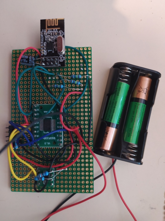
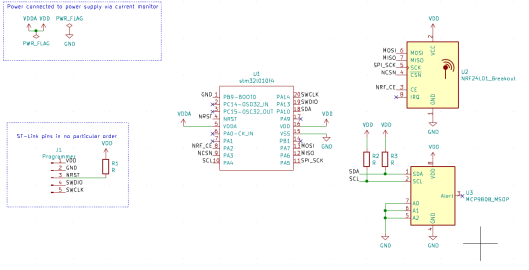
The table above shows the pins I need to connect. I’ve got 16 data bits, which I will connect Port B, as none of the Port B pins are connected to anything on the Discovery board. CS, RS, WR, RD, and RST are connected to pins PA1, PA2, PA3, PA4, and PA5 respectively. BL will be connected straight to +ve for now. This will be fun on a breadboard…
I have copied over a couple of functions from the demo code as shown below (with modifications for my pin-outs).
#define DATAOUT(x) GPIOB->ODR=x

#define LCD_CS_SET HAL_GPIO_WritePin(CS_GPIO_Port, CS_Pin, GPIO_PIN_SET)
#define LCD_RS_SET HAL_GPIO_WritePin(RS_GPIO_Port, RS_Pin, GPIO_PIN_SET)
#define LCD_WR_SET HAL_GPIO_WritePin(WR_GPIO_Port, WR_Pin, GPIO_PIN_SET)
#define LCD_RD_SET HAL_GPIO_WritePin(RD_GPIO_Port, RD_Pin, GPIO_PIN_SET)
#define LCD_RST_SET HAL_GPIO_WritePin(RST_GPIO_Port, RST_Pin, GPIO_PIN_SET)

#define LCD_CS_CLR HAL_GPIO_WritePin(CS_GPIO_Port, CS_Pin, GPIO_PIN_RESET)
#define LCD_RS_CLR HAL_GPIO_WritePin(RS_GPIO_Port, RS_Pin, GPIO_PIN_RESET)
#define LCD_WR_CLR HAL_GPIO_WritePin(WR_GPIO_Port, WR_Pin, GPIO_PIN_RESET)
#define LCD_RD_CLR HAL_GPIO_WritePin(RD_GPIO_Port, RD_Pin, GPIO_PIN_RESET)
#define LCD_RST_CLR HAL_GPIO_WritePin(RST_GPIO_Port, RST_Pin, GPIO_PIN_RESET)

#define WHITE       0xFFFF

#define u16 uint16_t
#define u8 uint8_t

#define LCD_W 320
#define LCD_H 480

#define USE_HORIZONTAL      0
#define LCD_USE8BIT_MODEL   0

typedef struct
{
        u16 width;
        u16 height;
        u16 id;
        u8 dir;
        u16 wramcmd;
        u16 rramcmd;
        u16 setxcmd;
        u16 setycmd;
}_lcd_dev;
_lcd_dev lcddev;

void LCD_write(uint16_t VAL) {
  DATAOUT(VAL);
  LCD_WR_CLR;
  LCD_WR_SET;
}

void LCD_WR_REG(u16 data) {
  LCD_RS_CLR;
  LCD_write(data);
}

void LCD_WR_DATA(u16 data) {
  LCD_RS_SET;
  LCD_write(data);
}

void LCD_WriteReg(u16 LCD_Reg, u16 LCD_RegValue) {
  LCD_CS_CLR;
  LCD_WR_REG(LCD_Reg);
  LCD_WR_DATA(LCD_RegValue);
  LCD_CS_SET;
}

void LCD_RESET(void) {
  HAL_Delay(50);
  LCD_RST_CLR;
  HAL_Delay(100);
  LCD_RST_SET;
  HAL_Delay(50);
}

void LCD_direction(u8 direction) {
  lcddev.setxcmd = 0x2A;
  lcddev.setycmd = 0x2B;
  lcddev.wramcmd = 0x2C;
  lcddev.rramcmd = 0x2E;
  lcddev.dir = direction % 4;
  switch (lcddev.dir) {
  case 0:
    lcddev.width = LCD_W;
    lcddev.height = LCD_H;
    LCD_WriteReg(0x36, (1 << 3));
    break;
  case 1:
    lcddev.width = LCD_H;
    lcddev.height = LCD_W;
    LCD_WriteReg(0x36, (1 << 3) | (1 << 6) | (1 << 5));
    break;
  case 2:
    lcddev.width = LCD_W;
    lcddev.height = LCD_H;
    LCD_WriteReg(0x36, (1 << 3) | (1 << 6) | (1 << 7));
    break;
  case 3:
    lcddev.width = LCD_H;
    lcddev.height = LCD_W;
    LCD_WriteReg(0x36, (1 << 3) | (1 << 5) | (1 << 7));
    break;
  default:
    break;
  }
}

void LCD_WriteRAM_Prepare(void) {
  LCD_CS_CLR;
  LCD_WR_REG(lcddev.wramcmd);
  LCD_CS_SET;
}

void LCD_SetWindows(u16 xStar, u16 yStar, u16 xEnd, u16 yEnd) {
  LCD_CS_CLR;
  LCD_WR_REG(lcddev.setxcmd);
  LCD_WR_DATA(xStar >> 8);
  LCD_WR_DATA(0x00FF & xStar);
  LCD_WR_DATA(xEnd >> 8);
  LCD_WR_DATA(0x00FF & xEnd);
  LCD_CS_SET;

  LCD_CS_CLR;
  LCD_WR_REG(lcddev.setycmd);
  LCD_WR_DATA(yStar >> 8);
  LCD_WR_DATA(0x00FF & yStar);
  LCD_WR_DATA(yEnd >> 8);
  LCD_WR_DATA(0x00FF & yEnd);
  LCD_CS_SET;

  LCD_WriteRAM_Prepare();
}

void LCD_Clear(u16 Color) {
  uint32_t i;
  LCD_SetWindows(0, 0, lcddev.width - 1, lcddev.height - 1);
  LCD_RS_SET;
  LCD_CS_CLR;
  for (i = 0; i < 320 * 480; i++) {
    DATAOUT(Color);
    LCD_WR_CLR;
    LCD_WR_SET;
  }

  LCD_CS_SET;
}

void LCD_Init(void) {
  LCD_RESET();

  LCD_CS_CLR;
  LCD_WR_REG(0XF7);
  LCD_WR_DATA(0xA9);
  LCD_WR_DATA(0x51);
  LCD_WR_DATA(0x2C);
  LCD_WR_DATA(0x82);
  LCD_CS_SET;

  LCD_CS_CLR;
  LCD_WR_REG(0xC0);
  LCD_WR_DATA(0x11);
  LCD_WR_DATA(0x09);
  LCD_CS_SET;

  LCD_CS_CLR;
  LCD_WR_REG(0xC1);
  LCD_WR_DATA(0x41);
  LCD_CS_SET;

  LCD_CS_CLR;
  LCD_WR_REG(0XC5);
  LCD_WR_DATA(0x00);
  LCD_WR_DATA(0x0A);
  LCD_WR_DATA(0x80);
  LCD_CS_SET;

  LCD_CS_CLR;
  LCD_WR_REG(0xB1);
  LCD_WR_DATA(0xB0);
  LCD_WR_DATA(0x11);
  LCD_CS_SET;

  LCD_CS_CLR;
  LCD_WR_REG(0xB4);
  LCD_WR_DATA(0x02);
  LCD_CS_SET;

  LCD_CS_CLR;
  LCD_WR_REG(0xB6);
  LCD_WR_DATA(0x02);
  LCD_WR_DATA(0x22);
  LCD_CS_SET;

  LCD_CS_CLR;
  LCD_WR_REG(0xB7);
  LCD_WR_DATA(0xc6);
  LCD_CS_SET;

  LCD_CS_CLR;
  LCD_WR_REG(0xBE);
  LCD_WR_DATA(0x00);
  LCD_WR_DATA(0x04);
  LCD_CS_SET;

  LCD_CS_CLR;
  LCD_WR_REG(0xE9);
  LCD_WR_DATA(0x00);
  LCD_CS_SET;

  LCD_CS_CLR;
  LCD_WR_REG(0x36);
  LCD_WR_DATA(0x08);
  LCD_CS_SET;

  LCD_CS_CLR;
  LCD_WR_REG(0x3A);
  LCD_WR_DATA(0x55);
  LCD_CS_SET;

  LCD_CS_CLR;
  LCD_WR_REG(0xE0);
  LCD_WR_DATA(0x00);
  LCD_WR_DATA(0x07);
  LCD_WR_DATA(0x10);
  LCD_WR_DATA(0x09);
  LCD_WR_DATA(0x17);
  LCD_WR_DATA(0x0B);
  LCD_WR_DATA(0x41);
  LCD_WR_DATA(0x89);
  LCD_WR_DATA(0x4B);
  LCD_WR_DATA(0x0A);
  LCD_WR_DATA(0x0C);
  LCD_WR_DATA(0x0E);
  LCD_WR_DATA(0x18);
  LCD_WR_DATA(0x1B);
  LCD_WR_DATA(0x0F);
  LCD_CS_SET;

  LCD_CS_CLR;
  LCD_WR_REG(0XE1);
  LCD_WR_DATA(0x00);
  LCD_WR_DATA(0x17);
  LCD_WR_DATA(0x1A);
  LCD_WR_DATA(0x04);
  LCD_WR_DATA(0x0E);
  LCD_WR_DATA(0x06);
  LCD_WR_DATA(0x2F);
  LCD_WR_DATA(0x45);
  LCD_WR_DATA(0x43);
  LCD_WR_DATA(0x02);
  LCD_WR_DATA(0x0A);
  LCD_WR_DATA(0x09);
  LCD_WR_DATA(0x32);
  LCD_WR_DATA(0x36);
  LCD_WR_DATA(0x0F);
  LCD_CS_SET;

  LCD_CS_CLR;
  LCD_WR_REG(0x11);
  LCD_CS_SET;
  HAL_Delay(120);
  LCD_CS_CLR; /*  */
  LCD_WR_REG(0x29);
  LCD_CS_SET;

  LCD_direction(USE_HORIZONTAL);

  LCD_Clear(WHITE);
}
At this point, I’m not reading any values from the LCD, so I’ve not implemented any reading capabilities (to keep things easier for now). Also, I changed the write setup so that the CS pin needs to be set and unset before and after each register write because the way the demo code implemented it didn’t look correct (or at least it looked ineffecient).
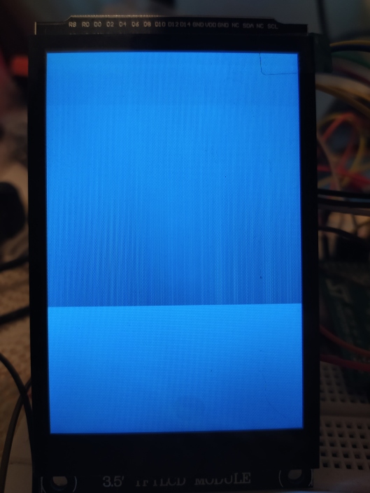
I then added this to a project file, and then called LCD_Init. And did it work…
No!
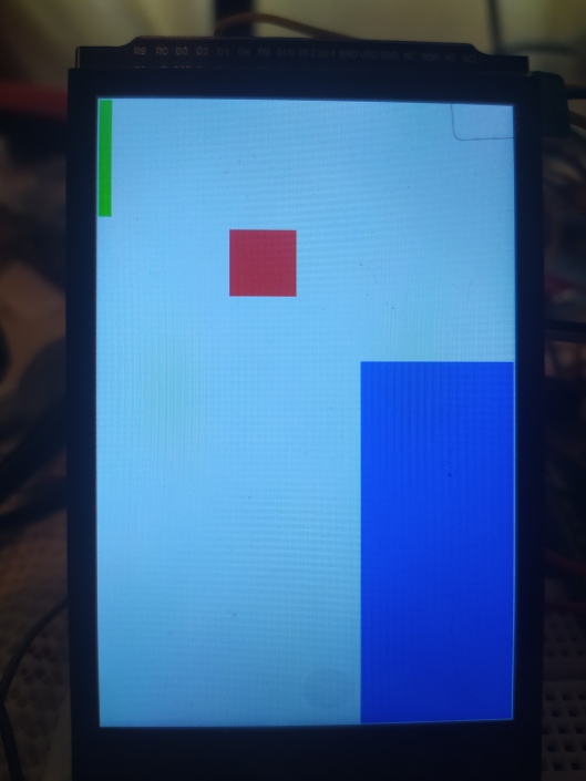
Above is the image on the LCD after trying to “clear” the screen (fill the screen with a single colour). It can’t be seen in the image, but the screen was also flickering a lot, looking like it was moving between the image below and something similar (but still wrong). I tried filling with different colours, but the results were similar, but with slightly different colour bars.
It then took me far to long to actually figure out the issue. I looked at different demo projects, read through the datasheet looking for something, and then tried something really small, which had a massive impact.
void LCD_Init(void){
  LCD_RD_SET;

  LCD_RESET();

  // The rest of the LCD_Init function, without change
}
That small addition of LCD_RD_SET made all the difference! It seems that the RD pin was being initialised as low, and since I wasn’t actually reading any data, I didn’t do anything with it. However, the LCD was expecting it to be high when writing.
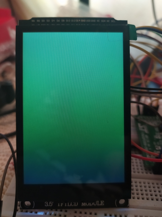
Now, when I try and clear the screen with a single random colour (this time 0x4321), I get the following:
Ignore the apparent colour change. That’s an artifact of my phone camera trying to take a picture of an LCD. From my point of view, when looked straight on, the screen is all a single colour of green.
So I can now set up the LCD, as well as fill the screen with a full block of colour. I’m not all the way there yet, but the screen is closer to being usuable for my home automation system.