
One of the things I’m currently working on is the ability to control the thermostat
“set point” both via a web-based UI and via the wall mounted thermostat itself.
The web-based UI is currently being created in Node-Red (more on that in a later entry), but the wall-mounted thermostat is currently working on an ESP8266. The idea is to have the following setup for the thermostat:
- The boiler on / off is still controlled by Node-Red
- The desired temperature can still be set using the web-interface from Node-Red.
- The desired temperature can also be controlled directly from the wall-mounted thermostat.
- The wall-mounted thermostat will contain:
- An ESP8266 which will communicate with Node-Red via MQTT
- A rotary encoder to control the current desired temperature
- A OLED display to show the current and desired temperature
I already have the temperature sensor working (and being sent via MQTT to node-red), and the OLED seems to be setup and working. Therefore, I’m currently working on getting the rotary encoder working on the ESP8266.
The encoder I’m currently working on is the KY-040, which is a rotary encoder and a push button in one. This will allow me to choose the desired current temperature (and later use the push button to go through menus, etc.). They are cheap enough (about 40p each), but as I quickly found out, READY bouncy.
Hardware
At the moment, I don’t have the button connected up, but the rotary encoder pins are connected to GPIO 4 and GPIO 5. Below shows the diagram of the whole setup to date, which now includes:
- ESP8266 nodemcu board
- DS1631 i2c temperature sensor IC
- 0.96″ OLED i2c display
- KY-040 rotary encoder
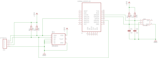
Simplified circuit diagram of system (excluding ESP setup).
I’ve left out most of the connection details for the ESP8266 as I’m using the nodemcu board which has all this setup (and I can’t actually find an EagleCad library that contains this particular board.
Simple enough and hopefully nothing too complicated. I’m sure there are ways I could clean up the circuit, but this will do for now.
Software
This one took my quite a bit longer than getting the hardware sorted out!
As this was my first attempt at using (cheap) rotary encoders, I stupidly thought that things would be quite easy to get working…
Attempt 1
My first attempt involved simply connecting one of the rotary encoders to a FALLING interrupt call, check the value of the other RE connection, decide if the rotary encoder had moved clockwise or anti-clockwise, and then print to serial within the interrupt call.
School-boy error! Don’t print to serial within interrupt calls. As should have been expected, the program crashed and reset everytime I turned the RE.
Attempt 2
So, second attempt was the same as above, but print to serial outside of the interrupt call.
This stopped the program from crashing, but as I did expect, the RE contacts were VERY bouncy, and the calculated position was all over the place! When turning clockwise, the calculated position was all over the place!
Getting better, but still no good.
Attempt 3
For the third attempt, I decided to get rid of the interrupt called, and poll the RE inputs. This allowed me to:
- Easily introduce de-bouncing into the code.
- Know if each input was pressed, had just been pressed, or had just been released.
The code for this was quite similar to what I had done for a previous project. In the git-hub project, the function for this is called checkButtons() I’m sure it could be refined, but for now it works.
For debouncing, I’m currently using 5ms, which seems to be working.
To check for the rotation of the RE, I used the same method as above. Meaning I’d check CLK for a fall (i.e. high to low) and check the value of the DT pin. If DT is high, then increase the position by 1 (i.e. clockwise). If DT is low, then reduce the position by 1 (i.e. anti-clockwise).
This seemed to work. When I turned the RE clockwise, I’d get a nice update in the number, but when I turned it anti-clockwise, it sometimes worked and sometimes didn’t work. Also, when I turned the RE fast, the numbers were all over the place, sometimes going back, sometimes forward. So getting better, but not quite there yet.
Also, increasing the debounce wait time didn’t seem to help, so I was starting to get a bit confused and had to do a bit more research.
Rotary Encoder LED Test
This got me thinking it would be good to test the RE more and see how it was actually working!
To do this, I connected the LEDs to the RE and rotated in both directions. What I found was that for 1 “click” in rotation, I had the following sequences:
- Clockwise:
- CLK {0 1 1 0}
- DT {1 1 0 0}
- Anti-clockwise:
- CLK {1 1 0 0}
- DT {0 1 1 0}
Now things are starting to make sense and I’m able to figure out some of my issues!
Attempt 4
So, now I know the pulse sequence for the RE, I was able to create a simple piece of code that stores the last 4 CLK and DT values, and update this each time the RE is rotated.
Then, only increase or decrease the current position after the correct set of sequences.
Upload the code and…
IT WORKS!!!
No bouncing problems. The values only go up when they should go up and only go down when they should go down. If I rotate the encoder, it sometimes doesn’t update. However, this is better than going in the wrong direction!
Progress
After working on the code a bit more, I now have a system where I can:
- Choose the current desired temperature using the rotary encoder, in steps of 0.5C.
- Whenever the desired temperature changes, it is sent to node-red via MQTT.
- Whenever the desired temperature is changes in node-red, it also sends the new value to the ESP via MQTT.
This took a lot longer than it should, but it seems to be working well for now.
You can see the REALLY messy circuit below. The OLED shows the current temperature (in the larger text) and the desired temperature (in smaller text further down).
The code and circuit diagram for this should now be available on the Github project page.

Circuit including OLED and Rotary Encoder
Next step
The next step is to add some functionality to the button on the rotary encoder. It would be good to get more details from the HA on node-red to display to the OLED (such as the current “Scene”, a menu).

Very good post!
Looking for your source code to try on my 8266 (adafruit)
Can’t seem to find the git-hub for it.
Can you help?
Thanks
https://github.com/nerobot/Home-Automation/blob/master/ESP8266TemperatureSensor/Main/Main.ino
I would like to get the source code too.. I spent a lot of time searching for good source code for encoder but your idea sounds best, but no code link 😦
thanks in advance 🙂
Found by looking through is other posts to find his github user, then dug around to find this specific project: https://github.com/nerobot/Home-Automation/blob/master/ESP8266TemperatureSensor/Main/Main.ino
I was looking for some help with ESP rotary programming but I’m using Lua so the theory is good but have to reapply it.
Hi,
How it is going with lua and OLED & Rotary Encoder? Did something? Currently I am working on similar project and would be happy to save some time by utilising someones pieces of code.
Aidas
I did actually get mine working very similar to this example: rotary encoder to choose a temperature displayed on an oled. Here’s my rotary.lua test script to accept input values from the encoder. https://github.com/domwrap/UtiLUAties/blob/master/rotary.lua
From there it’s fairly easy to update the oled using its own libraries. I don’t have a separate example, but it is embedded in my own thermostat TherMCU project https://github.com/domwrap/TherMCU/blob/master/thermcu.lua.
It’s all object oriented so hopefully you can piece the bits together you need. It’s mostly in trotary.lua and thermcu.lua, and oled control in toled.lua.
Sorry for the late replies as Ive been unable to work on anything for quite a while.
I’m now back to making, but for the moment, I’m moving away from the idea of using the rotary encoder and OLED display. Instead I’m currently working on making a low power wireless temperature sensor, which will then move onto a low power, solar charged, wireless weather station.